features

[For beginners] Self-study column by TAKISAWA staff: What is lathe? -About spindle-

other

2022.08.30

#Beginner

#Human resource development

#Lathe manufacturer

The previous column explained the outline of a lathe using a machine configuration schematic view.
Today, as announced in the previous column, spindle will be deeply explained!
Also, as before, indicators will be explained using the TCN-2100 product catalog.

Click here to look back the previous column.
[For beginners] Self-study column by TAKISAWA staff: What is lathe?
 

Let’s review the previous column. Do you remember what a spindle is?
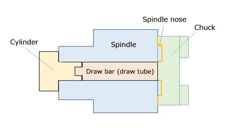
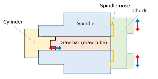
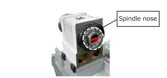
Spindle is “a shaft that rotates a workpiece attached to it”.
As it is an important component directly linked to machining accuracy, it must rotate quietly and smoothly as its basic characteristics.

1. Spindle mechanism

First, the three keywords related to spindle are explained below.

Chuck: Attached to the spindle nose to hold a workpiece.
Cylinder: Operates to open and close the chuck.Many are hydraulically or pneumatically operated.
Draw bar (draw tube): Connects the chuck and the cylinder.

Fig. 1 Spindle schematic diagram

The spindle has a chuck at the front end and a cylinder at the rear end. They are connected with a draw bar.

Next, let’s check the movement.

The spindle performs two types of movements.
The first is opening/closing of the chuck, and the second is rotation.
The two movements are explained below.

2. Chuck opening/closing movement

A workpiece is clamped by moving the chuck with the cylinder.

Fig. 2 Schematic diagram of chuck opening/closing movement

When clamping a workpiece, many parts are interlocked!
This diagram shows the O.D clamping movement. The red arrows indicate the chuck closing (clamping) movement, and the blue arrows indicate the chuck opening (unclamping) movement.

3. Rotation

Motor rotation is transmitted to the spindle via the belt,causing the spindle to rotate.
The actual schematic view is shown below.

Fig. 3 Spindle schematic view

In Fig. 3, the black long, narrow component at the bottom is the spindle motor.
The component in the upper center is the spindle, and the belt and motor pulley are on the left of it.
In this figure, the belt, which seems to be broken in the middle, certainly forms a loop.
An enlargement of the upper left portion is shown below.

Fig. 4 Spindle pulley and belt

The black strip is the belt, and the component receiving it is the spindle pulley.
As shown in Figs. 3 and 4, the belt is routed around the motor pulley and the spindle pulley to transmit the motor rotation to the spindle.

Comparing the schematic diagram and the actual photo may have helped you to understand the spindle mechanism.

4. Explanation of indicators

Table 1 Indicators listed in TCN-2100 catalog

Here are explanations about Spindle speed, Spindle nose (nominal code), and Spindle through-hole diameter, which are the most important indicators among the spindle-related items listed in Table 1.

Spindle speed: The number of revolutions of the spindle per unit time
The unit time “min-1” in Table 1 is an SI unit (international unit) indicating rotation speed, which means revolutions per minute.
Example: 3200min-1means that the number of spindle revolutions per minute is 3200.

Spindle nose (nominal code): The spindle contour, which receives a faceplate, chuck, and center.
It is surrounded by the broken white line in Fig. 4 below.
There are different types of spindle nose, such as A2-6 and Φ80F.

Spindle through-hole diameter: The diameter of the hole through the spindle. It is indicated in red in Fig. 4.
When considering machining of a workpiece penetrating the spindle, check the through-hole diameter.

Fig. 4 Spindle through-hole

How was today’s explanation?

Please look forward to the next column, which will explain the turret-related items!

Many terms have appeared also in this column!
They are explained on the page below.
Click below to learn more!

Machine Tool Terminology https://www.takisawa.co.jp/ir/words.html

Click here for TCN-2100